
 1 – Objective
The B.RCLab aims to provide the necessary equipment and expertise to perform radiometric characterization of instruments, with a high relevance to support climate research. The wavelength scale calibration facility is mainly designed for instrumentation performing spectral measurements, typically: a monochromator, a spectrograph as well as the special case of AOTF (Acousto-Optic Tunable Filter).
The objective of this facility is to verify and calibrate the wavelength scale of an instrument. For monochromators and spectrographs, it is the relationship between an electronic signal (or a parameter) and the real wavelength of the electromagnetic field that is studied, while for AOTF, it is the correspondence between the radiofrequency (RF) and the wavelength that will be transmitted by the crystal.
The wavelength scale of an instrument is generally temperature dependent due to thermal effects of opto-mechanical elements and this dependence must be addressed.
2 – Scientific rationale
2.1 – The dispersion of light and wavelength selection
The photochemical processes that take place in the Earth and planetary atmospheres are wavelength dependent. Moreover, the spectral distribution of the solar irradiance varies strongly with the wavelength as well. Therefore, most of scientific instruments designed for atmospheric studies and solar irradiance measurements rely on an optical element that diffracts the incoming light so that each wavelength can be measured separately.
These instruments are typically monochromators (using a rotating dispersing element, generally a grating, to produce a focused spectrum on the exit) and spectrographs (fixed grating, array detector illuminated by a focalized spectrum). The new generation of instruments uses AOTF, which is a birefringent crystal excited by an ultrasonic acoustic wave, acting as tunable filter.
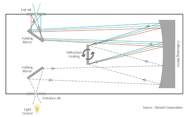
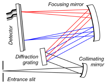
Figure 1. Operating principle of a monochromator with a rotating plane grating (left) and a spectrograph (right).
2.2 – The instrumental function
Spectrometers and spectrographs use an input slit of finite width, and their dispersing element also has a finite dimension. Consequently, a purely monochromatic incident light will present a spreading in the focal plane at the output of the instrument. This corresponds to the concept of the instrumental function, or slit function, which determines the bandwidth and spectral resolution of the instrument.
The image observed in the focal plane corresponds to the convolution between the natural spectral width of the incident monochromatic light and the instrumental function. It is recommended to characterize a slit function for a set of wavelengths sampling the spectral range under investigation, in order to obtain an accurate knowledge of the spectral variation of the width and the shape of this function.
3 – Methodology
3.1 – Wavelength calibration of monochromators and spectrographs
For monochromators, the wavelength scale consists of a one-to-one relationship between the stepper motor position driving the rotation of the grating and the wavelength emerging from the exit slit. For spectrographs, the wavelength calibration corresponds to the identification of the central wavelength reaching each pixel of a detector. For both kind of instruments, the methodology consists in using spectral lamps that deliver peak wavelengths (emission lines), well-tabulated (within a given uncertainty). These are typically hollow cathode lamps, arc lamps and laser lines.
Thanks to the numerous atomic elements available for the cathode or as a lamp bulb filled with gas, a large set of individual lamps providing a lot of spectral lines can be used for wavelength scale calibrations. It is indeed required to optimize the sampling over a spectral range, to better detect possible anomalies in a wavelength scale. Multiple diffraction order of selected single spectral lines, as produced by the instrument when order rejection filters are inactivated, can greatly increase the set of available atomic lines. However, the sensitivity of the instrument under test could also be an issue.
For example, hollow cathode lamps are known to have low emission, and maybe not be suitable for the wavelength calibration of specific monochromators and spectrographs. In addition to spectral lamps, a liquid filter can also be used to provide tabulated reference wavelengths. In this case, the reference is no more atomic lines but the transmission peak of a liquid in a cell. However, this device is more suitable for wavelength calibration of a spectrophotometer.
Notes:
- For monochromators driven by factory software, the wavelength selection is obtained from a software interface where low level electronic parameters (as a stepper motor position) are generally not accessible. In that case, the wavelength calibration will be adjusted thanks to a correction function that will characterize the discrepancy between the embedded and the real wavelength scales.
- A spectral lamp should be positioned very close to an entrance slit to optimize the input flux. However, if the lamp is not well aligned on the optical axis of the instrument, it will induce a systematic error due to the resulting non-nominal incident angle on the grating. This is why we systematically use a Teflon diffuser in front of the entrance slit to homogenize the incident light.
- For monochromators driven by factory software, the wavelength selection is obtained from a software interface where low level electronic parameters (as a stepper motor position) are generally not accessible. In that case, the wavelength calibration will be adjusted thanks to a correction function that will characterize the discrepancy between the embedded and the real wavelength scales.
Examples of application
Figure 2 shows the wavelength calibration performed for the space qualified spectroradiometer SOLAR/SOLSPEC. In that case, a direct link between the stepper motor position and the wavelength (nm) could be established. It is worth to mention that only intense He-Ne laser lines (at all order of diffraction) could be used for this instrument.
Figure 2. Wavelength calibration of the three channels of the SOLAR/SOLSPEC space instrument.
Figure 3 shows the wavelength scale study of a double monochromator designed for visible (VIS) and near-infrared (NIR) measurements at a fixed bandwidth of 10 nm. Using VIS-NIR spectral lines from various lamps, combined with a monochromatic and tunable NIR light beam for wavelengths larger than 2.6 µm, it was possible to fully characterize the (quite large) discrepancy between the actual wavelength scale and the scale embedded in the user interface (software) of the double monochromator. The uncertainty of the correction to be applied is around 0.5 nm, which is acceptable regarding the 10 nm bandpass.
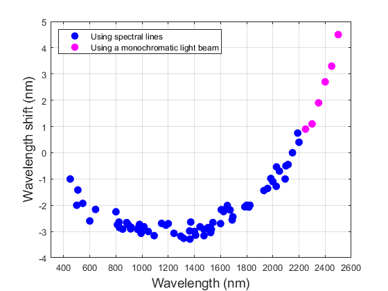
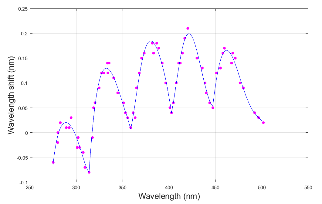
Figure 4 shows a wavelength scale calibration for which the accuracy of both wavelength shifts and distortion measurements are optimized using a large set of atomic lines from discharge and hollow cathode lamps. The instrument tested was a spectroradiometer using double monochromators for ground-based solar UV-VIS spectral irradiance measurements. In that case, an accurate scientific output such as the determination of the UV index, for example, requires a wavelength scale accuracy limited to a typical value of 0.05 nm.
The figure illustrates subtle distortions of the instrument, probably due to eccentricity of the gratings rotation mechanism. Thanks to the set of atomic lines available at B.RCLab, it was possible to characterized in detail the wavelength scale in the 275 nm – 500 nm spectral range and reduce the uncertainty to 0.02 nm after wavelength shift correction.
3.2 – Wavelength calibration of AOTF
The relationship between the RF and the transmitted wavelength of an AOTF is also temperature dependent. The resulting equation to characterize is the following: where is the radio frequency, is the temperature of the crystal and is the desired wavelength to be transmitted. This function presents a non-linear dependence in but could be approximated by a sixth order polynomial equation, for which each coefficient will be linearly dependent on temperature.
The wavelength calibration of an AOTF is specific and spectral lamps will not be used. Instead, for a given temperature, the AOTF must be illuminated by a stabilized light source providing a continuum emission, typically a Quartz Halogen Lamp (QTH) powered by stabilized DC current. The measurement of the wavelength transmitted by the AOTF for a given RF must be performed using a spectrometer.
Of course, the wavelength calibration of this spectrometer must be previously certified (with a documented standard uncertainty). The peak of the measured spectrum will correspond to the wavelength transmitted by the AOTF for each selected RF. The B.RCLab provides the required light source and calibrated UV-VIS-NIR spectrometer to perform these characterizations. See also the temperature dependence section in 3.4.
3.3 – Slit function characterization
As explained in Section 2.2, the spectrum of a single atomic (or laser) line as measured by a monochromator (or a spectrograph) is the convolution between the natural line width and the spreading effect of the instrument. A real measurement of the instrument function should correspond to the use of an infinitely narrow atomic line (acting as the identity for the convolution), which is not physically possible.
However, if the spectral resolution of the instrument is around one order of magnitude greater than the natural line width, then the spectrum of a single line remains a very good approximation of the instrumental function. However, an advanced data processing is possible to apply corrections, as described in Bernhard G. Opt. Eng. 44(4), 041011 (2005).
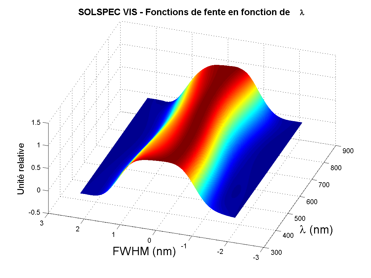
An example of application is the slit function characterization performed for the UV, VIS and NIR channels of the SOLAR/SOLSPEC space experiment, equipped with concave holographic gratings. Figure 5 presents the result of this characterization and illustrates the variation in shape and width observed as a function of wavelength for the VIS channel. It was obtained by interpolation between slit functions measured at various wavelengths.
3.4 – Temperature dependence
To extend the study of wavelength calibration to the temperature dependence, a dedicated equipment is required to regulate the temperature of the instrument under test. For further information, please refer to the Small TVAC section.
4 – Available equipment for wavelength calibration
4.1 – Spectral lamps
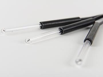
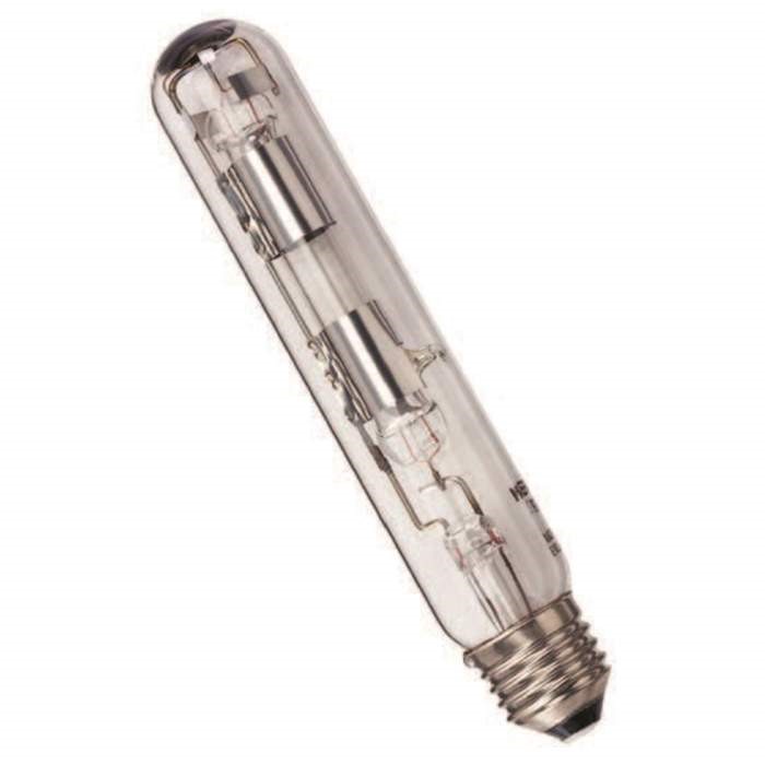
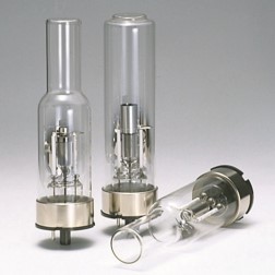
There are three models of spectral lamps available: pen-ray type lamps, larger bulb spectral lamps and hollow cathode lamps.
- Pen-ray lamps: small and versatile lamps that can easily be used in an optical assembly. At B.RCLab, spectral lines from rare gases and metal vapor are available for the following elements:
Ar, Kr, Xe, Hg and the combination Hg-Ne.
Consequently, the UV-VIS-NIR spectral range is covered (typically from 230 nm to 2000 nm).
- Large bulb spectral lamps: generally more intense than the pen-ray lamps. They are supplied at 0.9 A. The laboratory is equipped with the following lamps:
Zn, Hg, Cd, Ar, Xe, Kr, Rb, Na, He and the combination Hg-Zn-Cd.
The UV-VIS-NIR spectral range is also covered (typically from 210 nm to 2300 nm).
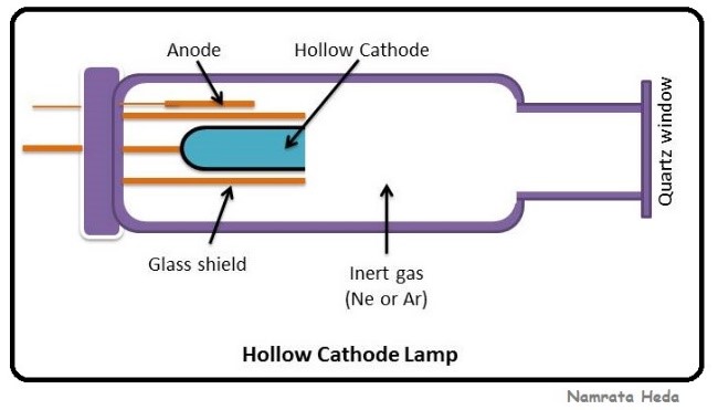
- Hollow cathode lamps: these discharge lamps consist of a cathode made from the desired atomic element, an anode and an inert gas contained in the glass envelope of the lamp. The spectral lines come from the filler gas atoms, which are ionized when a voltage is applied, and from the sputtered atoms from the cathode, excited in the plasma. The following element are available at B.RCLab facility.
As, Cs, Sb, Cd, Sn, Si, Ni, Te, Hg, Ba and Rb
The inert gas is generally Ar or Ne.
These lamps provide generally a low intensity, no continuum, and a large number of weak spectral lines. An advanced use of the available set of lamps can deliver virtually spectral lines for every 5 nm interval in the UV and VIS spectral range, and help for accurate wavelength calibration if the instrument under test is sensitive enough.
4.2 – Laser lines
The following laser lines are available from He-Ne emissions: 543.37 nm, 593.93 nm, 611.80 nm, 632.82 nm and the NIR line at 1523 nm. A dual wavelength He-Cd laser is also available, with spectral lines at 325 nm and 442 nm.
4.3 – Liquid filter
One liquid filter is available in our facility. It consists of a solution of holmium and didymium (praseodymium and neodymium in HClO4 (model 667045 from Hellma Analytics). The cell provides a broadband spectrum by transmission with very well-defined peaks in the UV-VIS spectral range. All 22 peaks are well detected for an instrument having a spectral resolution of 1 nm or better. The set of wavelengths available is the following: [241, 278, 287, 333, 347, 354, 361, 416, 444, 451, 468, 482, 512, 522, 537, 241, 844] nm.
4.4 – Monochromatic and tunable light beam
The combination of a 1000 W QTH lamp (or Xe arc lamp for higher UV intensity) and a double monochromator produces a monochromatic and tunable light beam system. The output of the spectrometer can be equipped with an optical fiber or a collimator. In this case, an infinite number of ‘spectral lines’ can be provided, thanks to the tunable selected wavelength delivered by the spectrometer. The spectral purity is high thanks to the use of a double monochromator and its high level straylight rejection. However, the bandwidth of the monochromatic beam produced depends on the slit width of the spectrometer and is of course wider than the width of the atomic lines. The limitation is of the order of 0.2 nm bandwidth. The wavelength selected is also strictly dependent on the accuracy of the spectrometer’s wavelength scale calibration. The B.RCLab can deliver monochromatic and tunable light beam between 200 nm and 2600 nm, or even 3500 nm if a fiber optic is not used at the output. The uncertainty of the selected wavelength is ±0.1 nm between 400 nm and 1100 nm, and ±0.25 nm for wavelengths larger than 1100 nm.
4.5 – Sun light
An alternative way to proceed to a wavelength calibration is to use the solar spectrum whose numerous absorption lines are well characterized, identified, and accurately measured from space (solar reference spectra). In this case, if the solar spectrum is measured by the instrument under test, an advanced software can be used to apply shift and stretch corrections to the measured spectrum until the solar line structures match the tabulated lines of a solar reference spectrum. The result of this process highlights the instrument user on the inaccuracy of the wavelength scale that can then be corrected. This process applies to the UV (for λ > 290 nm) and VIS spectral range. The Sun light is available in the laboratory using a fiber optic system. However, it is currently not operational.
4.6 – Summary
|
Available equipment |
Specifications (atomic elements) |
Spectral range or set of wavelengths (nm) |
|
Spectral lamps |
Pen-rays: Ar – Kr – Xe – Hg – Hg-Ne |
230 – 2000 |
|
Large spectral lamps: Zn – Hg – Cd – Ar – Xe – Kr – Rb – Na – He – Hg-Zn-Cd |
210 – 2300 |
|
|
Hollow cathode lamps Cathode: As – Cs – Sb – Cd – Sn – Si – Ni – Te – Hg – Ba – Rb Inert gas : Ar or Ne (depending on the lamp) |
||
|
Laser lines |
He-Ne He-Cd |
543.37 – 593.93 – 632.82 – 1523 325 – 442 |
|
Liquid filter |
Holmium and didymium |
241 – 278 – 287 – 333 – 347 – 354 – 361 – 416 – 444 – 451 – 468 – 482 – 512 – 522 – 537 – 241 – 844 |
|
Monobeam |
Double monochromator combined to a Xe arc lamp or a tungsten lamp |
200 – 3500 |
|
Sun light |
Use of the solar spectral lines |
290 – 800 |
5 – Uncertainty of wavelength calibration
The uncertainty of wavelength calibration is generally dependent on the bandwidth. For a typical bandwidth of 1 nm, it is possible to reduce the uncertainty to 0.02 nm for fine studies in the UV-VIS. Nominal uncertainties are in the range of 0.05 nm to 0.1 nm for wavelengths shorter than 1 µm. In the NIR (1 µm to 3.5 µm), the uncertainty is of the order of 0.1 nm to 0.25 nm. In a general way, for accurate characterizations, the uncertainty can be limited to 1/10 – 1/20 of the width if the slit function.
|
Wavelength calibration Spectral range (nm) |
Typical uncertainty in wavelength calibration (nm) |
|
General studies* |
Typically: from ±0.05 nm to ±0.1 nm |
|
Advanced studies* 300 – 800 |
Optimized to ±0.02 nm |
|
NIR** 1000 – 3500 |
Typically: from ±0.1 nm to ±0.25 nm |
|
General consideration |
|
|
Uncertainty of wavelength calibration: about 1/10 to 1/20 of the width if the slit function |
|
* For bandwidth of the instrument under test of about 1 nm or lower
** For bandwidth generally larger than 1 nm in the NIR


