

Some applications require the use of areas with high cleanliness levels to expose equipment to minimum contamination. B.RCLab counts with a certified ISO-5 area (class 100) under a laminar flux constituted by six independent modules (Figure 1).
The external limits are surrounded by soft-walls made of several layers of anti-static transparent vinyl to allow low outgassing. The room surrounding the laminar flux is a certified ISO-7 area. One of the modules of the laminar flux is used as a grey zone surrounded by a secondary soft-wall, to enter to the clean area. The total working area is around 6 m2, currently cointaining an optical table, a vacuum chamber of 420 L, and a horizontal laminar flux typically used for installation/uninstallation procedures.
Only a maximum of two people are allowed inside the laminar flux at the same time. Temperature, relative humidity and pressure are monitored in real time thanks to calibrated sensors inside the cleanroom.

Figure 1. Schematic diagram of the ISO-5 area.
The optical setup available at the cleanroom was developed for absolute and relative radiometry characterization of detectors within a spectral range from 0.4 to 2.65 µm, that can be cooled down inside the large TVAC if necessary. The optical setup mainly consists of a 1000 W QTH lamp, a DTMc300 double monochromator, and an integrating sphere of 13.5 cm in diameter. It provides a tunable monochromatic flux with a straylight rejection of 10-8 and a uniform light beam (up to 2 %) at the output of the integrating sphere. The accuracy of the wavelength scale is ±0.1 nm between 400 nm and 1100 nm, and ±0.25 nm for wavelengths larger than 1100 nm.
Moreover, thanks to the combination of different neutral density filters disposed in two independent filter wheels, up to 30 different levels of illumination over 4 orders of magnitude can be provided at the output beam. An electronic shutter implemented at the entrance of the monochromator allows persistence measurements.
The stability of the lamp can be monitored by a multichannel filter radiometer located at the output of the light source, and by an available set of PbS and Si calibrated photodiodes located at the secondary output of the monochromator and the two additional ports of the integrating sphere. An additional InGaAs calibrated photodiode at the integrating sphere allows continuous light monitoring. Figure 2 shows a schematic diagram of the VIS-NIR characterization facility and some pictures of its components. More detailed information can be consulted in doi.org/10.1117/1.JATIS.9.3.036001.

Figure 2. Schematic diagram of the radiometric characterization facility located at the ISO-5 area.
Absolute radiometry is possible because the optical power available at each of the outputs of the integrating sphere was characterized with the calibrated photodiodes, and a homogeneity matrix (Figure 3) was derived at the working plane of the facility (where the detector would be located). The working plane was set at 85 mm from inside the viewport of the vacuum chamber and therefore the optical alignment is critical.

Figure 3. Homogeneity matrix obtained at the working plane of the facility and generated by the integrating sphere, averaged for all wavelengths.
The facility was used to characterize the flight and spare models of the VIS-NIR detectors of MAJIS/JUICE. Figure 4 shows a list of measurements that can be performed with the complete setup.
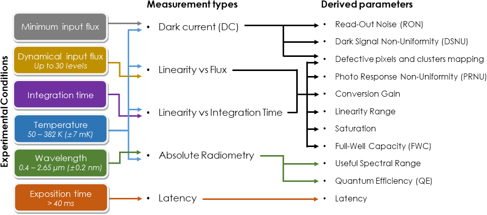
Figure 3. Measurements and parameters that can be derived by the VIS-NIR characterization facility.
To avoid the light absorption due to atmospheric vapor water at NIR wavelengths, the light path of the optical setup is flushed with N2, generated at a flow of 0.6 L/min. The cryocooling system implemented to thermalize the detectors at cryogenic temperatures and provide dark conditions, is described in Laboratory/Large TVAC. Besides real time monitoring and logging of relevant quantities, the facility can be remotely operated from the control room by the Optical Ground Support Equipment (OGSE) developed in a LabVIEW environtment.
Depending on the type of measurements to be performed, the operator can remotely configure the characterization facility to optimize the timing for data acquisition during a typical characterization campaign. The only element that must be manually adjusted is the width of the variable slits of the double-monochromator to tune its bandpass to the required settings. Additionally, a webcam allows the visualization of the entrance slit of the monochromator. The radiometric data acquired by the OGSE is continuously backed up in the BIRA-IASB servers.
For the MAJIS VIS-NIR detectors characterization, a focusing array was developed to provide the beam convergence of 11° that the detector should receive from the collimating optics in the flight instrument. This array was developed in colaboration with Lambda-X (Figure 4). It is assembled between the integrating sphere and the viewport of the vacuum chamber, and consists of the combination of two concave off-axis mirrors and an elliptical tilted aperture between both mirrors. The collimating optics re-image the output of the integrating sphere on the detector sensitive area with a beam homogeneity within 1 %. Optical alignment is also critical.

Figure 4. Focusing array implemented for the characterization of the MAJIS/JUICE VIS-NIR detector in its final configuration.


