

1. Objectives and scientific rationale
1.1. Angular response and field of view
The objective is to characterize the angular response and the field of view of an instrument designed for light measurement. Generally, such instrumentation includes an entrance optics to collect the photon flux and transfer it to the internal component and its detector. The optics defines a Field Of View (FOV), which ensures light collection in a correct geometry.
In other words, it represents the maximum angle of view in which the instrument is able to detect incoming photon flux. The characterization of the instrumental response within this FOV, compared to the one observed on the optical axis, corresponds to the concept of angular response. The response variation observed within the FOV will characterize the angular response.
The facility designed for FOV and angular response characterization aims to rotate the instrument in front of a light source (or inversely), using accurate optical alignment and the instrument response. The extinction of the instrumental response for a given angle of incidence determines the FOV. The response change observed within the FOV will characterize the angular response. This FOV could present a circular symmetry (no dependence of the FOV widening as a function of the rotation around the optical axis). In that case, only one meridian plane must be characterized. Otherwise, the FOV must be characterized with respect to a directional plane.
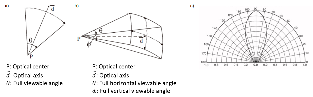
For instruments designed to measure solar global irradiance (spectral or wavelength-integrated), such as pyranometers, multi-channel filters radiometers or spectroradiometers, the entrance optics must be designed to collect the incident light from all direction of the hemisphere (solid angle of 2π steradian). This response is obtained using a diffuser or an integrating sphere. Indeed, a natural surface unit on Earth receives the direct solar irradiance (depending on the elevation angle of the Sun), coupled with diffuse irradiance from all directions. For any line of sight, the irradiance collected by the surface unit along this axis is weighted by a factor corresponding to the cosine of the angle with respect to the zenith.
Therefore, the entrance optics of an instrument designed for global irradiance measurements should ideally present a cosine response. This is usually not the case, therefore angular corrections should be applied during the data processing to retrieve the global irradiance. These corrections are based on a laboratory angular characterization that requires accurate determination of the angular response, as well as its deviation to the cosine ideal response (spectrally if required) within the whole FOV (2π by design). This deviation is named Cosine Angular Response.
For instruments presenting a limited FOV (2° or 8° for example), as it is the case for direct Sun measurements or trace species monitoring using DOAS (Differential Optical Absorption Spectroscopy) methodology, it is required to check (in addition to the FOV characterization) whether the instrument response is constant or not within this FOV. It is related to flat field characterizations. Typical entrance optics use a diffuser combined to a baffling system or a lens that focalizes the light on a fiber bundle. The flat field response may reach a high level (quasi-constant response within the FOV) or not, and must be characterized.
This introduction was developed and illustrated in the case of ground-based instrumentation but the B.RCLab has the capability to perform similar characterizations in an ISO-5 clean area on a space qualified payload (a CubeSat for example).
1.2. BRDF measurement
The purpose is to describe how light is reflected and diffused on an opaque and rough surface in all directions, depending on the light incidence. The results are compiled in a function called Bidirectional reflectance distribution function (BRDF). This function disposes of four (or potentially five due to the wavelength dependence) variables:
- the zenith and azimuthal angles (θi, Φi) describe the direction of the light incidence (it can be a collimated beam),
- (θr, Φr) characterize the direction of the reflected light,
- (λ) describes the spectral dependence of the reflectance when using a monochromatic incident light beam.
BRDF measurements must be motorized and automated due to the large number of points required for angular exploration, either for the position of the incident light source surrounding the sample or for the reflectance of the sample. The name of the measurement device is gonioreflectometer. Accurate optical alignment is required to adjust the height and orientation of the sample placed in the center of two concentric hemispheres associated to the rotation of the light source and the detector.
It is expected to develop a BRDF facility at B.RCLab in the course of 2023. It will allow the characterization of surface for ground-based or space projects, such as carbon nanotubes, optical solar reflectors or painting.
2. Methodology
The methodology describes only the FOV and angular characterizations.
The main principle implemented at B.RCLab is to rotate the Device Under Test (DUT) in front of a light source. We simply use a facility equipped with a motorized rotating plate. However, an accurate optical alignment is mandatory because the axis of the rotating plate must be tangent to the first optically active surface of the DUT. Moreover, the orthogonal and centered position on the optical path of the light source must be well defined to perform the angular characterization in angular unit relative to the zenithal position. The methodology described here is typically for a DUT equipped with a diffuser as entrance optics, and designed for measurements over 2π sr (e.g. a pyranometer).
Additional configurations will be described further. The accurate optical alignment is achieved using a laser, jigs, targets and reticles, and following a well-defined procedure. To summarize, jigs are used to put the rotation axis tangent to the flat surface of the entrance optics. The target is used to align and center the laser orthogonal to this optics. Finally, the reticle is used to align the light source on the optical axis represented by the laser beam.
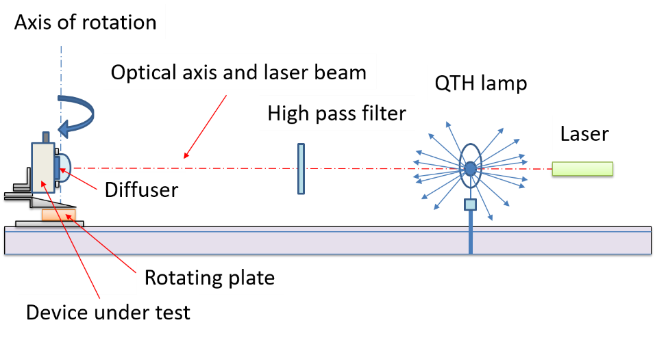
At this B.RCLab facility, the light source is a 1000 W Quartz-Tungsten Halogen (QTH) lamp, stable but uncalibrated because the measurement can be performed along a relative scale. This lamp covers the UV, VIS and NIR spectral ranges and can be used for polychromatic illumination. For the characterization of a DUT such as a pyranometer, it is recommended to use a light source that mimics as much as possible the solar spectrum, or at least to simulate the ozone cut-off that occurs around 290 nm for ground-based solar irradiance. A high-pass filter centered around 300 nm (for the 50 % transmission) is used for that purpose (Figure 2).
If a spectral distribution closer to the solar spectrum, or more UV radiation is needed, it is recommended to use a collimated Xenon arc lamp (solar simulator) as the light source. The bench must be automated to allow a DUT rotation following a pre-defined angular sampling. The angular sampling is generally finer for large tilt angles, for example between 75 and 90°.
Finally, after the characterization, the response of the DUT will be analyzed with respect to the signal obtained for the orthogonal position, and the relative response (or the deviation to the cosine ideal response) can be retrieved in the selected meridian. If the angular response requires another meridian (at least a second one, at 90° of the first one), the DUT must be reinstalled and realigned in the required position. Generally, the DUT presents a good azimuthal homogeneity of the angular response.
When a large and heavy DUT must be characterized for its angular response, it becomes obvious to rotate the light source rather than the instrument. In that case, it is usual to rotate a QTH lamp in a horizontal plane, and fixed on a mechanical arm.
As described above, regarding instruments designed for light measurements within a narrower FOV, the angular characterization is very similar, except that additional care is required to align the axis of rotation on the first optically active surface. Indeed, this surface is generally less apparent and accessible, such as a lens in its holder or a diffuser inside a tube equipped with baffles. It is also not necessary to scan the angular response over 180°, but only to characterize the signal cut-off that will define the FOV boundary and the angular response within this FOV.
The signal extinction at the boundary of the FOV can be characterized following criteria, such as a drop to a given signal threshold, normalized to the signal at orthogonal incidence. This threshold can be fixed to 80 %, 50 %, 5 % or the retrieval of the Dark Current (DC) level.
Up to now, the methodology was described for polychromatic (white light) illumination, using a lamp providing a continuum. However, it is possible to target several spectral ranges on demand. The easiest solution is to use bandpass filters in front of the white light source, with narrow (2-3 nm or less), moderate (10 nm to 40 nm) or broad (more than 100 nm) bandwidth. It could be used, for example, to characterize the angular response of a multi-channel filters radiometer.
Concerning the characterization of the entrance optics of a spectroradiometer, a white light source can be used but it will be recommended to characterize the angular response for a large set of wavelengths due to a possible spectral dependence of its response. In addition, the characterization could also depend on the temperature (as it could be the case for some Teflon diffuser), but the tests performed at B.RCLab are at room temperature. However, it could be possible (on demand) to develop further the facility in order to provide a thermal control of the DUT.
Examples of application
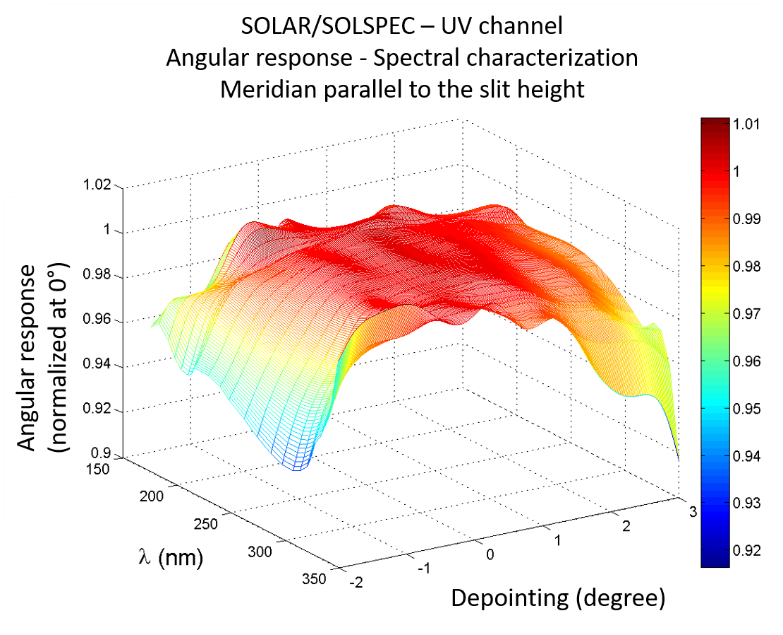
This first example illustrates the angular characterization of the UV channel of SOLAR/SOLSPEC. In that case, the study was performed as a function of the wavelength. Results presented in Figure 3 were obtained for an angular response exploration along a meridian parallel to the entrance slit height. This slit is covered by frosted quartz diffusers to homogenize the response within the narrow (a few degrees) FOV of this space instrument designed for direct Sun spectral irradiance measurements. The flat field response was therefore well characterized.
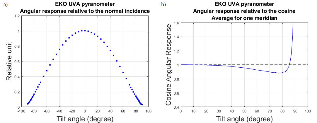
The second example presents the angular response characterization of a UVA pyranometer from EKO (Japan) designed for ground-based global UVA solar irradiance measurements. The methodology described previously was applied using a QTH lamp filtered by a high-pass filter to mimic the ozone cut-off. Figure 4 shows the angular response in a single meridian after its normalization to the response observed for a normal light incidence, and the deviation to the cosine ideal response.
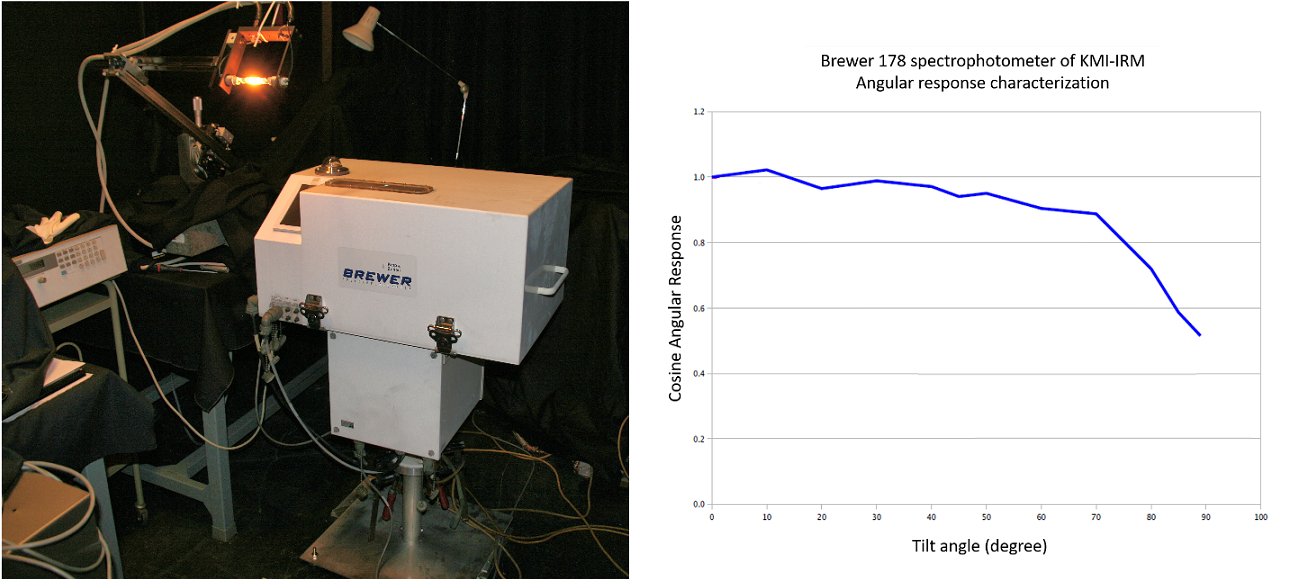
The third example presents the angular characterization performed through a BIRA-IASB/KMI-IRM collaborations. The instrument, a Brewer spectrophotometer, was designed for ozone abundance and solar spectral irradiance measurements. Given the size and weight of the instrument, a customized setup was assembled to allow the lamp to rotate around the instrument. The cosine angular response is presented in Figure 5.
3. Available facilities
The main available facility is called ARF (for Angular Response Function). This optical bench uses mainly the equipment described in Figure 2: a motorized rotating plate, a 1000 W QTH lamp, all items for optical alignment, and a filter holder to select a useful spectral range (or to simulate the ozone cut-off). The angular sampling can be predefined according to the requirements. These settings are saved in a text file. Figure 6 shows the rotating plate and a general view of the facility, with a pyranometer as the DUT.
This facility is designed for the characterization of quite lightweight instrument (pyranometer, radiometer, small entrance optics as a telescope, small sensors, …). The weight limitation is of about 5 kg. The uncertainty for mechanical alignment using the laser beam spot and the rotational motion are 1 mm and 1 arc minute, respectively. Additional light sources can be used if required. For instance, a 30 W deuterium lamp or a 150 W Xe arc lamp if stronger UV flux is needed. The broadband spectral range is typically 200 nm – 3500 nm.
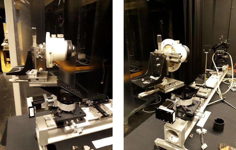
For heavier instrumentation, the approach is different. After its optical alignment, the light source must perform smooth and well-controlled rotation around the instrument optical axis over a maximum range from -90° to +90°. We generally use a 1000 W QTH lamp. This light source can be fixed on a rotating arm, as seen in Figure 5, or installed on a customized optical mount (not motorized in that case) as presented in Figure 7.
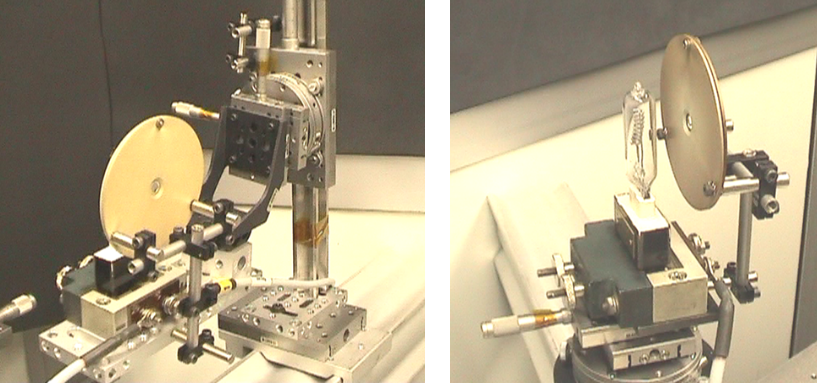
Table 1 summarizes the available equipment at B.RCLab for angular characterization.
|
Available equipment
|
Specifications (for angular response and field of view study) |
Uncertainty
|
Comments
|
|
ARF facility |
Angular range: From -90° to +90°. |
± 1 arc minute |
Motorized rotation. Exploration of one meridian. Fixed light source, rotation of the instrument. |
|
Angular sampling: Predefined (settings in a text file). |
N/A |
Automated acquisition. Limitation to instrument. weight < 5 kg. |
|
|
Light sources:
|
N/A |
Depending on the need of strong UV illumination or not. |
|
|
Spectral range:
|
Depending on the light source and the use of filters. |
||
|
Optical alignment: |
± 1 mm |
Using a laser beam. |
|
|
Customized facility (for heavier instrument) |
Adjustment of the bench design, to allow the alignment and rotation of the lamp around the optical axis of the entrance optics.
|
||


